
GCC oilfield and high-temperature components
Inconel 625 & 718 machining for demanding service
For deep-well valve trim, sour-gas equipment and high-temperature burner nozzles, alloy choice is only part of the specification. Reliable parts also depend on controlled machining, verified material, critical-dimension inspection and documentation ready for project review.
PartsMake manufactures Inconel 625 and Inconel 718 components using multi-axis CNC milling, turning, mill-turn, grinding and EDM for oilfield MRO contractors, flow-control specialists and industrial package integrators across Saudi Arabia, the UAE, Qatar and the wider GCC.
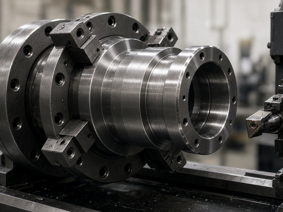
Machining planned around the component
Material condition, geometry, critical features and inspection requirements inform the process route and cutting strategy.
Material selection
Choosing between Inconel 625 and 718
Both are nickel-based alloys for demanding service, but they are not interchangeable. Selection depends on operating temperature, loads, media, manufacturing route and the applicable project specification.
For sour-gas service, confirm material condition and hardness requirements against the project specification, including NACE MR0175/ISO 15156 where specified. Alloy selection alone does not establish compliance.
Corrosion-focused applications
Inconel 625
Offers strong corrosion resistance in a range of aggressive environments, including chloride-bearing media, with good resistance to pitting and stress-corrosion cracking in specified conditions. It also retains useful strength at elevated temperatures.
Common fit: valve trim, fluid-handling components, corrosion-exposed hardware and exhaust-system parts.
Strength and fatigue-focused applications
Inconel 718
After precipitation hardening, provides high strength with good fatigue and creep performance for demanding elevated-temperature service. Its corrosion resistance suits many industrial applications.
Common fit: high-load valve components, shafts, housings and hot-section hardware.
Inconel 625 is often considered where corrosion resistance is a primary requirement; Inconel 718 is frequently considered where mechanical strength and fatigue performance are central. Actual suitability depends on grade condition, heat treatment, service environment and design limits. Share compliance criteria at RFQ stage so they can be reviewed against your approved requirements.
Process control
Keep the cut stable. Protect the critical features.
Inconel work-hardens and retains heat around the cutting zone. When a tool rubs instead of cutting, the surface can harden locally, accelerating insert wear and making later passes less predictable. Thin walls, interrupted cuts and tight internal features add further risk.
No one-size-fits-all parameter chart
A long valve stem, thin-walled nozzle and heavy valve body place different demands on tool choice, feed, setup and chip control. Parameters are confirmed for the specific operation.
01 / Cutting strategy
Controlled speed and feed
Use low, controlled cutting speeds and a stable chip load matched to the tool grade, operation and material condition. Keep the edge cutting rather than dwelling or rubbing.
02 / Machine setup
Rigidity and torque
Match feed strategy to a rigid, high-torque machine setup. Stable workholding helps limit vibration, deflection and chatter.
03 / Tooling and coolant
Wear-resistant cutting tools
Select carbide tooling and suitable edge geometry for the operation and cut length. High-pressure through-tool coolant can be used where compatible with the machine setup to support heat and chip control.
04 / Pass planning
Account for work hardening
Plan stock allowance and the order of critical features around the alloy, supplied condition, geometry and inspection needs.
Machining capacity
CNC processes for Inconel 625 & 718 parts
The suitable route depends on drawing, material size, tolerance stack and production quantity. Combining operations can reduce setup changes and help maintain critical relationships.
| Manufacturing process | Published work envelope | Typical use |
|---|---|---|
| 5-axis simultaneous milling | Up to 1,200 × 1,000 × 800 mm | Complex ports, angled passages, impeller features and multi-face valve components |
| Heavy-duty CNC turning | Up to Ø850 × 2,200 mm | Shafts, mandrels, sleeves, spools and turned pressure-containing parts |
| Mill-turn machining | Up to Ø420 × 1,050 mm | Components requiring turning and milled features in a coordinated setup |
| Large gantry milling | Up to 3,500 × 2,200 × 1,000 mm | Large bases, plates and structural interfaces |
| CNC cylindrical grinding | Up to Ø400 × 1,500 mm | Precision diameters, bearing seats and sealing surfaces |
| Wire EDM | Up to 600 × 400 × 350 mm | Slots, profiles and features in difficult-to-machine sections |
| Die-sinking EDM | Up to 800 × 600 × 450 mm | Deep cavities and small features with limited conventional tool access |
Published process capability references include ±0.005 mm for 5-axis milling and mill-turn work, ±0.008 mm for heavy turning and ±0.002 mm for cylindrical grinding. These are not a substitute for confirming achievable tolerances on the actual drawing.
Component applications
From deep-well valve trim to burner nozzles
Manufacture can be based on customer-approved drawings and requirements. For MRO work, a model, worn part or marked-up drawing can help clarify fit and interfaces; reverse-engineered dimensions should be reviewed and approved by the customer before manufacture.
Oilfield and flow control
Deep-well valve trim and sour-service parts
For contractors replacing worn trim, rebuilding a valve or sourcing drawing-controlled components for a specific pressure and media envelope.
- Valve stems, seats, cages, plugs and trim
- Sour-gas wellhead spools and mandrels
- Pump shafts, sleeves and fluid-handling details
- High-pressure manifolds and instrument housings
- Custom parts from customer drawings or approved samples
At RFQ, identify alloy grade and condition, hardness limits, pressure class, service media and required standards. Include sealing details, surface finishes and the inspection and test plan for safety-critical or pressure-containing parts.
Combustion and exhaust systems
Burner nozzles and hot-section hardware
Exhaust-gas and flare-system components may face elevated temperatures, oxidation, thermal cycling and aggressive process gases. Orifice and passage geometry can affect flow and equipment performance.
- Exhaust and combustion-system burner nozzles
- Orifice components and flow-control inserts
- Nozzle bodies and instrumented housings
- High-temperature brackets and mounting hardware
- Replacement components for existing assemblies
Specify operating temperature range, gas composition, flow requirements, connection details and erosion or corrosion allowances. For a critical flow profile, provide controlling dimensions and the required inspection method.
Quality and traceability
Inspection records planned with the order
Documentation can vary between an MRO replacement, an EPC package and an operator-controlled project. Identify required data book contents before production so inspection and traceability scope can be reviewed.
Material identification
EN 10204 3.1 material certificates linked to heat or lot identification.
Chemistry verification
PMI by XRF/OES to verify material chemistry.
Dimensional evidence
CMM inspection data books for drawing-critical dimensions and dimensional inspection using calibrated metrology equipment.
Testing coordination
NDT coordination and testing, including PT, MT and UT where specified.
Hydrostatic pressure testing
Available up to 20,000 PSI (1,380 bar), subject to component and test requirements.
Up to 20,000 PSI
A 3.1 certificate, PMI report and CMM report serve different purposes. State which are mandatory. For sour-service parts, provide acceptance criteria and any heat-treatment or hardness documentation required by the end user.
Route selection
Choose the process around the functional surfaces
Geometry, batch size, material condition and the features that control function determine the manufacturing route.
- 5-axis millingFor complex valve bodies, multi-angle ports and parts suited to machining multiple faces in fewer setups.
- Turning / mill-turnFor concentric features, shafts, mandrels and parts combining turned diameters with milled details.
- GrindingFor sealing diameters, bearing surfaces or roundness requirements needing a finer finish or closer control.
- EDMFor narrow slots, deep features or difficult profiles impractical for conventional cutting tools.
Review before releasing stock
Drawing review is especially useful where parts include thin walls, deep bores, tight positional tolerances or extensive material removal. Share the latest revision and identify critical-to-function features early.
Built for GCC project requirements
Parts can be supplied to industrial customers in Dammam, Jubail, Riyadh, Musaffah, Abu Dhabi, Dubai and Doha. Shipment to site or an industrial hub can be discussed, including customs and conformity-document coordination.
For Saudi-bound shipments, advise whether SABER/SASO documentation is required and identify the importer of record. UAE and other GCC destinations may have separate customs, VAT and conformity requirements. Delivery terms, shipping mode and documentation scope are confirmed against destination and shipment details.
Project questions
Get the specification details clear
A few details can make an Inconel machining review more useful from the outset.
Request a quotation
Send your Inconel 625 or 718 machining requirements
Share the information below for a technically useful review and quotation.
- 1. Drawing or 3D model, including revision and units
- 2. Alloy grade and required material condition
- 3. Quantity, target delivery date and destination
- 4. Critical dimensions, fits, surface finishes and tolerances
- 5. Service conditions, including temperature, pressure and media
- 6. Required certifications, PMI, inspection records, NDT or pressure tests
- 7. Applicable sour-service, operator or project specifications
For drawing clarification or an RFQ package, include your company name, project location and preferred delivery terms.
Email: info@partsmake.ae
Address:
Send your enquiry
Include the part details and project requirements for an informed manufacturing review.