
Liquid cooling for GCC AI infrastructure
Liquid Cooling Cold Plates for AI Data Centres in the GCC
Keep high-density AI workloads running in the Middle East’s demanding climate. Micro-channel cold plates transfer heat directly from processors and accelerators, helping data-centre operators move beyond the limits of air cooling.
Designed for ambient temperatures above 50 °C, continuous rack loads and regional operating conditions, our custom plates pair low thermal resistance with pressure-drop-conscious channel geometry.
150–600
W/cm² sustained heat-flux range*
< 1 × 10⁻⁹
atm·cc/s helium leak rate
12–18
working days for first articles
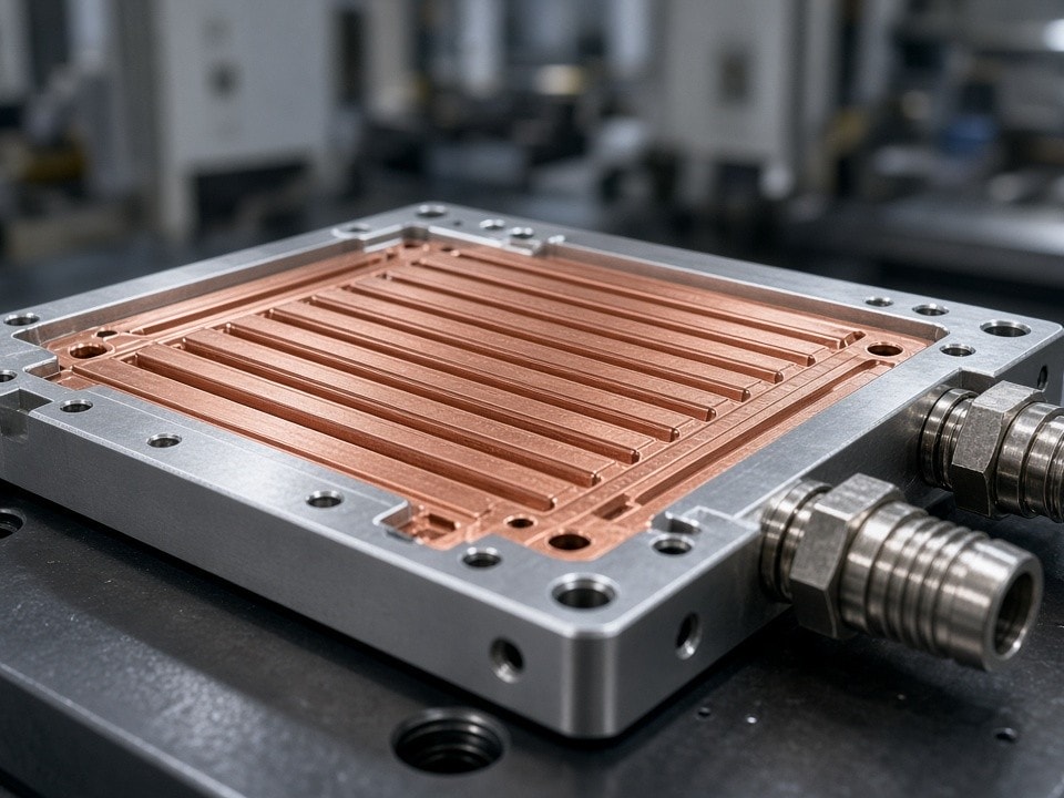
Thermal performance engineered around your chip footprint
*Typical sustained heat flux varies by material, geometry and operating conditions. Final performance is confirmed against project requirements.
How the design works
Micro-channels, built for demanding workloads
Heat removal at the chip
Coolant passes through narrow channels directly beneath the processor or accelerator. This geometry reduces thermal resistance while keeping pressure drop low enough for standard facility pumps.
Considered for regional conditions
Material selection and plate design account for airborne salts, inhibited glycol coolant and dimensional stability through wide daily temperature swings in desert environments.
Materials and typical parameters
Choose the substrate for your thermal and weight targets
High-purity aluminium offers lower weight with suitable corrosion resistance when paired with inhibited glycol mixtures. Oxygen-free copper provides higher thermal conductivity for the hottest GPU and accelerator modules.
| Parameter | Aluminium 6063 / 1050 |
|---|---|
| Channel width | 0.4–1.2 mm |
| Fin height | 2–6 mm |
| Wall thickness | 0.3–0.6 mm |
| Maximum plate size | 600 × 400 mm |
| Heat flux (sustained) | 150–350 W/cm² |
| Internal pressure test | 15 bar / 30 min |
| Helium leak rate | < 1 × 10⁻⁹ atm·cc/s |
| Parameter | Oxygen-Free Copper C101 |
|---|---|
| Channel width | 0.3–0.8 mm |
| Fin height | 1.5–4 mm |
| Wall thickness | 0.25–0.5 mm |
| Maximum plate size | 500 × 350 mm |
| Heat flux (sustained) | 250–600 W/cm² |
| Internal pressure test | 20 bar / 30 min |
| Helium leak rate | < 1 × 10⁻⁹ atm·cc/s |
Typical supplied parameters; final dimensions and performance are confirmed against the approved design. All plates receive CMM inspection of channel geometry and hydrostatic or helium leak testing before shipment.
Manufacturing approach
A joined and machined assembly, without avoidable leak paths
Vacuum brazing joins the cover and base without filler alloys that could restrict channels or create leak paths. The process avoids flux inclusions associated with torch or furnace methods.
01 · Substrate and join
High-purity aluminium or oxygen-free copper
The cover and base are vacuum brazed to preserve open flow passages and reduce the risk of micro-leak paths.
02 · Finish the flow geometry
5-axis micro-milling
Internal fin arrays and manifold ports are finished to the required surface and tolerance. Asymmetric channel layouts can be machined to match specific chip footprints without secondary welding.
03 · Inspect and verify
Documented checks before shipment
CMM inspection verifies channel geometry, followed by hydrostatic or helium leak testing. This inspection and test process supports the specified pressure-test and leak-rate requirements.
Project fit
Custom batches for integrators and EPC contractors
Skid builders and hardware integrators supporting NEOM, G42-linked facilities and large solar-plus-compute sites can request small batches of custom cold plates with short lead times.
Start with a drawing or STEP file
PartsMake provides DFM feedback within 24 hours. Finished plates can be supplied with EN 10204 3.1 material certificates, CMM reports and leak-test records ready for site handover.
GCC delivery and documentation
Clear records from approved drawing to site
- Neutral-crate packing with laser-etched part numbers.
- Shipments to JAFZA, DAFZA, Dammam or Musaffah, with SABER/SASO documentation and DDP terms when requested.
- Typical cycle from approved drawing to site delivery: 12–18 working days for first articles and 8–12 working days for repeat orders.
Request a quote
Let’s size a cold plate for your AI workload
Send your current cold-plate drawing, target heat load, coolant type and required quantity. We’ll reply with a firm price and lead time based on the exact geometry and material.
For urgent prototypes, include “RFQ – AI Liquid Cooling” in the subject line.